Theoretical Analysis
of a Carbon-Carbon Dimer Placement Tool for Diamond Mechanosynthesis
Ralph C. Merkle†*, Robert A. Freitas Jr.‡
Zyvex Corp., 1321 North Plano Road,
Richardson, Texas 75081, USA
† Mailing Address: 1134 Pimento Ave., Sunnyvale CA, 94087
USA; Email: merkle@merkle.com
‡ Mailing Address: P.O. Box 605, Pilot Hill CA, 95664 USA; Email:
rfreitas@rfreitas.com
* Author to whom correspondence
should be addressed.
******************************************************************************
The original version of this paper was submitted for publication on 9 October 2002, accepted for publication on 17 February 2003, and published in August 2003. The preferred literature citation is the following (or equivalent):
Ralph C. Merkle, Robert A. Freitas Jr., “Theoretical analysis of a carbon-carbon dimer placement tool for diamond mechanosynthesis,” J. Nanosci. Nanotechnol. 3(August 2003):319-324.
Please note that the online document may differ slightly from the published original. The permanent URL of this document is: http://www.rfreitas.com/Nano/DimerTool.htm
The original HTML abstract of this paper is available here.
The PDF version of this paper is available here.
******************************************************************************
Abstract
Density functional theory is used with Gaussian 98 to analyze a new family of proposed mechanosynthetic tools that could be employed for the placement of two carbon atoms – a CC dimer – onto a growing diamond surface at a specific site. The analysis focuses on specific group IV-substituted biadamantane tool tip structures and evaluates their stability and the strength of the bond they make to the CC dimer. These tools should be stable in vacuum and should be able to hold and position a CC dimer in a manner suitable for positionally controlled diamond mechanosynthesis at room temperature.
Keywords: Adamantane, Carbon, Density Functional Theory, Diamond, Dimer, Mechanosynthesis, Nanotechnology, Positional Control
1. INTRODUCTION
Arranging atoms in most of the ways permitted by physical law is a fundamental objective of nanotechnology. A more modest and specific objective is the ability to synthesize a wide range of stiff hydrocarbons – including molecularly precise diamond structures – using positionally controlled molecular tools. Such positional control might be achieved using an instrument like a Scanning Probe Microscope (SPM). Several theoretical proposals for molecular tools have already been made.1-4 For example, the theoretical proposal of Drexler2 for a hydrogen abstraction tool appears feasible based on the ab initio investigations of Musgrave et al.1, the molecular mechanics investigations of Sinnott et al.5 and Brenner et al.,6 and other theoretical work.7-10 Previous proposals for various carbon deposition tools2, 3 have not yet been extensively explored theoretically.4, 11
In this paper, we propose and analyze new tools that might be useful in the precise placement of two carbon atoms (a carbon dimer) on a growing molecular structure. Two carbon atoms held together by a triple bond can – for many purposes – be treated as a single unit: a dimer. The function of a dimer placement tool is to position the dimer, then bond the dimer to a precisely chosen location on a growing molecular structure, and finally to withdraw the tool – leaving the dimer behind on the growing structure. To achieve this, the dimer is required to be (1) bonded relatively weakly to the tool and (2) highly strained and thus highly reactive so it will easily bond to the growing molecular structure to which it is added.
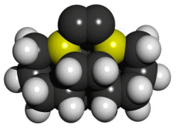
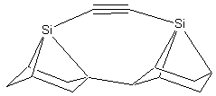
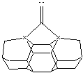
There is a large combinatorial space of possible tools that might satisfy both requirements. For those tools that are modeled here, we attempt to satisfy the two basic requirements by bonding the dimer to two group IV supporting atoms: carbon, silicon, germanium, tin, or lead. This series of elements forms progressively weaker bonds to carbon, so the proposed tools will likewise be progressively more weakly bound to the carbon-carbon (CC) dimer. The supporting group IV atoms are part of two substituted adamantane (C10H16) frameworks that position and orient them. The two substituted adamantane12 frameworks are rotated and fused together to make a biadamantane13 structure (Figure 1), creating very high angle strain in the bonds between the two supporting atoms and the dimer. This molecule, a bi-silaadamantane dicarbon, is only the tip of a complete tool. In a complete mechanosynthetic apparatus, a somewhat larger version of this molecule would likely be required so that the active tip could be held and positioned via a rigid handle structure.
Figure 1.
DCB6-Si dimer placement tool tip.
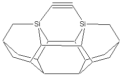
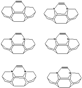
Three basic tool tip configurations are readily apparent (Figure 2) – a dicarbon bridge (DCB) motif (the subject of this paper) in which each Si atom is bound to two central carbon bridges, a monocarbon bridge (MCB) motif in which each Si atom is bound to a central bridge of two carbon atoms in the tool, and a “chevron” motif.
Figure
2. Dimer placement tool tips based on
dicarbon bridge (DCB), monocarbon bridge (MCB), and “chevron” motifs.
DCB
MCB
Chevron
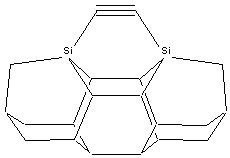
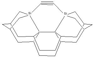
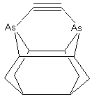
The aspect ratio of the dimer placement tool may be increased by substituting two 5-member rings at each shoulder of the tool tip (e.g., DCB5, MCB5), in place of the 6-member rings (DCB6, MCB6) which more closely resemble the bulk diamond (lonsdaleite) handle structure, thus slightly elevating the carbon dimer above the top of the shoulder at the cost of increased tip structure strain. Other details of the tip structure can also be varied. For example, the two group IV supporting atoms could be replaced with two group V elements, allowing the shoulder atoms to be entirely removed – which increases tool tip aspect ratio but may decrease tool tip rigidity (Figure 3). These and other tool tip structures that might be useful, along with the methods by which this family of tool tips might be chemically synthesized and then bound to an SPM tip, and spent tool tips recharged, will be described in future work.
Figure
3. DCB-As configuration of dimer
placement tool tip.
Density functional theory
(DFT) analysis suggests that the group IV substituted adamantane-derived
framework of highly reactive tools should be stable in vacuum prior to
interacting with any surface, and remains relatively weakly bonded to the dimer
while still orienting the dimer appropriately.
Each desired tool structure is a minimum on the potential energy surface
(PES). Most possible undesired
alternative tool structures are transition states or are not even stationary
points on the PES, though one tool variant considered here (DCB6-C) has an
unusually shallow minimum on the PES.
Figure 4. Six mechanosynthetic tool tip
variants for dimer placement tools (DCB6-C, DCB6-Si, DCB6-Ge, DCB6-Sn, DCB6-Pb,
and DCB6-SiGe).
Here, we investigate this
proposed new class of horizontal dimer placement tools by focusing on the six
particular tool tip structures shown in Figure 4, evaluating both their
stability and the strength of their bonding to the CC dimer.
2. COMPUTATIONAL METHODS
All six tool tip structures were evaluated
using DFT in Gaussian 98.14
Geometries involving carbon, silicon and germanium supporting atoms were
optimized using the B3LYP/3-21G* level of theory unless otherwise noted. Geometries involving tin and lead supporting
atoms were optimized using B3LYP/LANL2DZ.
The LANL2DZ basis set is specialized for dealing with high Z atoms
(beyond the third row). The stability
of the wave functions was verified using the STABLE keyword and the nature of
the stationary point was verified using a frequency calculation in all
cases. Single point calculations at the
B3LYP/6-311+G(2d,p) level of theory were used for energy calculations for
structures with carbon, silicon and germanium supporting atoms.
The accuracy of B3LYP/6-311+G(2d,p) // B3LYP/3-21G* energies should be adequate for the purposes considered here. A slightly lower level of theory (in which the geometry is optimized at HF/3-21G*) has a mean absolute deviation of 0.14 eV.15 We would expect that the slightly better level of theory used here would not have a worse mean absolute deviation. Thermal noise at room temperature is about 0.02 eV; in conventional positionally uncontrolled chemistry, errors on the order of 0.14 eV might well influence reaction rates and also the dominant reaction pathway taken when multiple alternative reaction pathways are present. However, in the context of the present analysis this should not be an issue because alternative reaction pathways are limited by using positional control. Encounters between the reactive tool tip and the growing workpiece take place only at the desired position and only in the desired orientation. Alternative pathways that might otherwise occur in solution when molecules encounter each other in multiple random orientations and positions are largely eliminated by this approach. In addition, we would expect that the relative accuracy of the very similar structures compared here would be significantly better than the absolute errors generated by comparison of dissimilar structures15 – the mean absolute deviation is computed from structures that are sometimes quite different.
The accuracy of the B3LYP/LANL2DZ level of theory has not been as extensively investigated. However, it is commonly used for studies of high Z atoms.15
3. RESULTS AND DISCUSSION
3.1. Stationary Points and Rearrangements
The results of tool tip energy calculations
are summarized in Table I.
Table I. Energy calculations for dimer placement tool molecules
having group IV atoms used as attachment points for CC dimer.
Tool Tip Configuration Energy (eV)
DCB6-C -23197.52
Carbene
rearrangement -23197.15 (diff: 0.37)
Discharged
DCB6-C -21123.60
CC -2065.32
CC
+ Discharged DCB6-C -23188.93
Minus DCB6-C 8.59
DCB6-Si -36882.22
Carbene
rearrangement: -36881.26 (diff: 0.96)
Discharged
DCB6-Si -34808.11
CC -2065.32
CC
+ Discharged DCB6-Si -36873.43
Minus DCB6-Si 8.79
DCB6-SiGe -85522.11
Discharged DCB6-SiGe -83448.49
CC dimer -2065.32
CC
+ Discharged DCB6-SiGe -85513.81
Minus DCB6-SiGe 8.30
DCB6-Ge -134161.98
Carbene rearrangement -134161.12 (diff: 0.86)
Discharged DCB6-Ge -132088.86
CC dimer -2065.32
CC
+ Discharged DCB6-Ge -134154.18
Minus DCB6-Ge
7.80
DCB6-Sn -21298.01
Carbene rearrangement -21297.27 (diff: 0.74)
Discharged DCB6-Sn -19226.27
CC dimer -2064.49
CC
+ Discharged DCB6-Sn -21290.76
Minus DCB6-Sn 7.25
DCB6-Pb -21301.01
Carbene rearrangement -21300.36 (diff: 0.65)
Discharged DCB6-Pb -19230.37
CC dimer -2064.49
CC
+ Discharged DCB6-Pb -21294.86
Minus DCB6-Pb
6.15
Singlet/triplet energy gap:
DCB6-Si 3.44
Carbene rearrangement 2.92
Notes:
DCB6-C, DCB6-Si, DCB6-SiGe, DCB6-Ge: Energies computed at B3LYP/6-311+G(2d,p) // B3LYP/3-21G* (single point at
B3LYP/6-311+G(2d,p) with zero-point correction from a frequency calculation at
the B3LYP/3-21G* level of theory) for structures all of whose heavy atoms are
C, Si, or Ge.
DCB6-Sn, DCB6-Pb: Energies computed at B3LYP/ LANL2DZ (with zero point correction at the
same level of theory) for all structures which include Sn or Pb atoms.
DCB6-Si singlet/triplet gap: Triplet energies computed at B3LYP/6-311+G(2d,p) triplet //
B3LYP/3-21G* singlet (without zero point correction).
Figure 5 shows the
three stationary points of primary interest – (A) the dimer placement tool with attached dimer, (B) the undesired
carbenic rearrangement of the basic tool, and (C) the tool after placement of
the dimer and after tool withdrawal from the surface. The element X can be carbon, silicon, germanium, tin or
lead. Other possibilities for X have
not been investigated in this paper.
The left and right instance of X can be different elements if
asymmetrical tool properties are desired, though we have only considered a
single example of this possibility here.
Note that points A, B, and C
represent states of the tool in isolation, and do not consider interactions
with a diamond surface. The present
paper focuses purely on the tool, and possible pathologies that could rule out
its use. Analysis of tool-surface
interactions is expected to require significant further effort and will be the
subject of a future paper.
Figure 5. Stationary points of interest for DCB6-X dimer placement tool analysis.
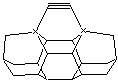

(A) (B)
(C)
For almost all choices of X investigated here, the undesired carbenic rearrangement is a transition state on the potential energy surface – a frequency analysis of the stationary point shows one imaginary frequency – while both the tool-with-dimer and the tool-without-dimer configurations are minima on the potential energy surface (all positive real vibrational frequencies). The one exception is when X = C, in which case the carbene form is a shallow minimum on the PES.
Table II. Energy required to remove the CC dimer from the tool
X Energy (eV) Level
of Theory
C 8.588 B3LYP/6-311+G(2d,p) //
B3LYP/3-21G*
Si 8.788 B3LYP/6-311+G(2d,p) //
B3LYP/3-21G*
SiGe 8.058 B3LYP/6-311+G(2d,p) //
B3LYP/3-21G*
Ge 7.802 B3LYP/6-311+G(2d,p) //
B3LYP/3-21G*
Sn 7.246 B3LYP/LANL2DZ //
B3LYP/LANL2DZ
Pb 6.148 B3LYP/LANL2DZ //
B3LYP/LANL2DZ
See
notes from Table I for calculational details.
Table II shows that the energy required to remove the CC dimer from the tool – the binding energy – can be selected by changing the supporting atoms. The binding energy is weakest using supporting atoms of lead. Progressing up the periodic table from lead to tin, germanium, and silicon, the binding energy of the DCB6-X dimer placement tool increases in magnitude.
Interestingly, the rising dimer binding energy slightly weakens when the supporting atoms are carbon rather than silicon. Some insight into this trend reversal at carbon may be gained by approximating the binding energy components. In Table III, the energy of the H3X-CCH bond proxies the energy required to break the two bonds between the carbon dimer and the supporting atoms (first column), and the energy of the H3X-XH3 bond proxies the energy gained when the two supporting atoms become free to bond to each other (second column). Subtracting the second column from twice the first column as a rough proxy for the dimer binding energy (third column) gives the same trend reversal at X = C as in Table II, indicating that the increase in binding energy from Si-Si to C-C may be substantially greater than the increase from Si-CC to C-CC, paradoxically reducing the dimer removal energy for X = C.
Table III. Proxies for the bond energy of supporting atoms on
discharged tip, supporting atom to dimer, and net dimer removal energy, using a
simple bond-energy model with Gaussian 98 (in eV).
X H3X-CCH H3X-XH3 Dimer Removal
C -5.30 -3.57 -7.03
Si -5.26 -2.99 -7.53
SiGe ---- -2.85 -7.21
Ge -4.80 -2.78 -6.82
Sn -4.61 -2.24 -6.98
Pb -4.18 -1.91 -6.45
See
notes from Table I for calculational details.
It is possible that the use of the DCB6-X tool with X = Si might be problematic on some diamond surfaces, given that the X = C tool has a slightly smaller binding energy which suggests that the dimer could remain adhered to the X = Si tool in favor of detachment. However, it is not clear that the X = C tool is a good proxy for any particular diamond surface. For example, two adjacent carbon radicals exposed on an otherwise hydrogenated diamond C(111) surface would interact only weakly. Such radicals would not behave as the two strongly interacting carbon support atoms in the X = C tool and thus should not weaken the attachment of the dimer to the C(111) surface – unlike the two supporting atoms in the X = C tool.
The energy difference between the horizontal dimer and the vertical (carbenic) forms is given in Table IV. In all cases but X = C, the carbene form is a transition state (one imaginary frequency). For X = C, the carbene form is a minimum on the PES (rather than a transition state).
Table IV. Energy difference between the horizontal dimer and the vertical (carbene) form.
X Energy (eV) Level
of Theory
C 0.37 B3LYP/6-311+G(2d,p) //
B3LYP/3-21G*
Si 0.96 B3LYP/6-311+G(2d,p) //
B3LYP/3-21G*
Ge 0.86 B3LYP/6-311+G(2d,p) //
B3LYP/3-21G*
Sn 0.74 B3LYP/LANL2DZ //
B3LYP/LANL2DZ
Pb 0.65 B3LYP/LANL2DZ //
B3LYP/LANL2DZ
A more careful investigation of the PES for the case of X = Si suggests an absence of unexpected stationary points in the immediate vicinity of the three structures already described: the horizontal dimer, the vertical dimer, and the tool without the dimer. Our expectation that the carbene (vertical dimer) rearrangement is a transition state was confirmed using frequency calculations at the higher B3LYP/6-31G* level of theory. Further analysis at the B3LYP/3-21G* level of theory starting from the vertical carbene transition state and following the eigenvector for that transition state (using the IRC keyword in Gaussian) and then minimizing showed that the two minima associated with the transition state are both the horizontal dimer form of the tool. That is, the vertical dimer carbene transition state connects two known stationary points: the two horizontal dimer structures. Finally, several candidate minima structures created using MM+ in HyperChem with conceivable but unusual bonding patterns all converged to one of the three stationary points already discussed.
It is difficult to
guarantee the absence of unexpected minima, and only the case of X = Si was
investigated more carefully in the present study. However, it appears that the three stationary points described –
the DCB6 with horizontal dimer (a minimum), the DCB6 with the vertical
(carbene) dimer (a transition state), and the DCB6 without the dimer (a
minimum) – define all of the relevant stationary points for X = Si, Ge, Sn, and
Pb. For X = C, there is an additional
transition state between the horizontal minimum and the vertical (carbene)
minimum. But because the X = C
structure will not be used as a tool, identification of this latter transition
state was not done. While we cannot
state with certainty that other stationary points do not exist, molecular
dynamics at the AM1 level did not reveal their presence.
3.2. Singlet/triplet Energy Gap
Beyond a more careful analysis of the stationary points of the DCB6 tools with X = Si, the singlet/triplet energy gap was also computed for this structure. Using the singlet-optimized B3LYP/3-21G* geometry for the DCB6-Si with horizontal dimer, the triplet/singlet energy gap was determined by comparing the single-point energies computed at the B3LYP/6-311+G(2d,p) level of theory without zero point correction for either the singlet or triplet energies for purposes of this comparison. Geometries were optimized at the lower level of theory in the singlet state, and the triplet single point energy at that geometry was then computed; see Table I. The singlet state is energetically preferred to the triplet state by a substantial margin: 3.44 eV for the horizontal dimer and 2.92 eV for the vertical dimer. This large energy gap suggests that the possibility of the system being in a triplet state at room temperature from thermal activation can be neglected.
3.3. Molecular Dynamics Simulation
Ab initio molecular dynamics simulations using gradient-corrected density functional theory and a plane-wave basis (using VASP: the Vienna Ab initio Simulation Package16) were carried out on the DCB6-Si dimer placement tool containing a carbon dimer attached to the two terminal silicon atoms (X = Si). The simulation, performed for 5 ps at an internal temperature of 1000 K, predicts the horizontal dimer structure should remain stable under conditions of moderately high temperatures. A further simulation of this tool using AM1 at a temperature of 900 K for 200 ps also did not result in any rearrangements.
Of course, single trajectories for 5-200 ps are
insufficient to ensure long-term stability of the dimer on the deposition
tool. As an additional check, the
Arrhenius equation for the one-step thermal desorption rate k1 = n exp(-Ed / kBT) may be
used to crudely approximate the canonical residence time for a CC dimer
attached to a tool tip heated to temperature T.17, 18 Taking T = 300 K, kB = 1.381 x 10⁻²³
J/K (Boltzmann’s constant), Ed = 6.148 eV for the weakest tool-bound
dimer (the DCB6-Pb tool, Table II), and
the pre-exponential constant n ~ kBT/h ~ 6 x 10¹² sec-1 (h =
6.63 x 10⁻³⁴ J-sec) typically used for thermally-migrating
chemisorbed hydrocarbon adatoms on diamond surface19-24 (the precise
value of which does not sensitively influence the conclusion), the lifetime of
the CC dimer against spontaneous dissociation from the tool tip is k1-1
~ 1090 sec.
4. CONCLUSIONS
The DCB6-X family of dimer placement tools, for X = Si, Ge, Sn and Pb, should be stable in vacuum when used at room temperature, and possibly at significantly higher temperatures. The CC dimer in these structures should remain oriented horizontally with a high probability. The proposed dimer placement tools should be able to hold and position a CC dimer in a manner suitable for positionally controlled diamond mechanosynthesis at room temperature.
The CC dimer is bound to these tools by progressively weaker bonds, moving from Si to Pb, facilitating release of the CC dimer from the tool and its attachment to a growing molecular structure. The chemical reactions by which these tools interact with and deposit a CC dimer on a growing diamond surface will be investigated computationally in future work.
References
and Notes
1. C. B. Musgrave, J. K. Perry, R. C. Merkle, and W. A. Goddard III, Nanotechnology 2, 187 (1991).
2. K. E. Drexler, Nanosystems: Molecular Machinery, Manufacturing, and
Computation, John Wiley & Sons, New York (1992).
3. R. C. Merkle, Nanotechnology
8, 149 (1997).
4. S. P. Walch and R. C. Merkle, Nanotechnology 9, 285 (1998).
5. S. B. Sinnott, R. J. Colton, C. T. White, and D. W. Brenner, Surf. Sci. 316, L1055 (1994).
6. D. W. Brenner, S. B. Sinnott, J. A. Harrison, and O. A. Shenderova, Nanotechnology 7, 161 (1996).
7. M. Page and D. W. Brenner, J. Am. Chem. Soc. 113, 3270 (1991).
8. M. Page and D. W. Brenner, in Proc. Second Intl. Conf. New Diamond Science and Technology, edited by R. Messier, J. T. Glass, J. E. Butler, and R. Roy, Materials Research Society, Pittsburgh, PA (1991), p. 45.
9. X. Y. Chang, M. Perry, J. Peploski, D. L. Thompson, and L. M. Raff, J. Chem. Phys. 99, 4748 (1993).
10. A. Ricca, C. W. Bauschlicher Jr., J. K. Kang, and C. B. Musgrave, Surf. Sci. 429, 199 (1999).
11. F. N. Dzegilenko, D. Srivastava, and S. Saini, Nanotechnology 9, 325 (1998).
12. IUPAC Commission on Nomenclature of Organic Chemistry, A Guide to IUPAC Nomenclature of Organic Compounds: Table 21. Saturated polycyclic hydrocarbons. Type 1 – unlimited substitution, Blackwell Scientific Publications (1993).
13. H. F. Reinhardt, J. Org. Chem. 27, 3258 (1962).
14. M. J. Frisch, G. W. Trucks, H. B. Schlegel, G. E. Scuseria, M. A. Robb, J. R. Cheeseman, V. G. Zakrzewski, J. A. Montgomery, Jr., R. E. Stratmann, J. C. Burant, S. Dapprich, J. M. Millam, A. D. Daniels, K. N. Kudin, M. C. Strain, O. Farkas, J. Tomasi, V. Barone, M. Cossi, R. Cammi, B. Mennucci, C. Pomelli, C. Adamo, S. Clifford, J. Ochterski, G. A. Petersson, P. Y. Ayala, Q. Cui, K. Morokuma, P. Salvador, J. J. Dannenberg, D. K. Malick, A. D. Rabuck, K. Raghavachari, J. B. Foresman, J. Cioslowski, J. V. Ortiz, A. G. Baboul, B. B. Stefanov, G. Liu, A. Liashenko, P. Piskorz, I. Komaromi, R. Gomperts, R. L. Martin, D. J. Fox, T. Keith, M. A. Al-Laham, C. Y. Peng, A. Nanayakkara, M. Challacombe, P. M. W. Gill, B. Johnson, W. Chen, M. W. Wong, J. L. Andres, C. Gonzalez, M. Head-Gordon, E. S. Replogle, and J. A. Pople, Gaussian 98, Revision A.11, Gaussian Inc., Pittsburgh, PA (2001).
15. J. B. Foresman and A. Frisch, Exploring Chemistry with Electronic Structure Methods: A Guide to Using Gaussian, Second Edition, Gaussian Inc., Pittsburgh, PA (1996).
16. G. Kresse and J. Furthmuller, Vienna
Ab-initio Simulation Package (VASP):
The Guide, VASP Group, Institut
fur Materialphysik, Universitat Wien, Sensengasse 8, A-1130 Wien, Vienna, Austria (2003).
17. C. Accary, P. Barbarat, W. L. Hase, and K. C. Hass, in Proc. Third Intl. Symp. on Diamond Materials, edited by J.P. Dismukes and K.V. Ravi, The Electrochemical Society, Pennington, NJ (1993), p. 178.
18. Th. Schaich, J. Braun, J. P. Toennies, M. Buck, Ch. Woll, Surf. Sci. 385, L958 (1997).
19. S. P. Mehandru and A. B. Anderson, Surf. Sci. 248, 369 (1991).
20. S. Skokov, B. Weiner, and M. Frenklach, J. Phys. Chem. 98, 7073 (1994).
21. E. J. Dawnkaski, D. Srivastava, and B. J. Garrison, J. Chem. Phys. 102, 9401 (1995).
22. E. J. Dawnkaski, D. Srivastava, and B. J. Garrison, J. Chem. Phys. 104, 5997 (1996).
23. M. Frenklach and S. Skokov, J. Phys. Chem. 101, 3025 (1997).
24. Y. G. Hwang, Y. H. Lee, J. Korean Phys. Soc. 33, 467 (1998).
******************************************************************************
last updated by the author on 6 October 2003